
Exploring the 1914 Kissel 4-40 Transmission
 |
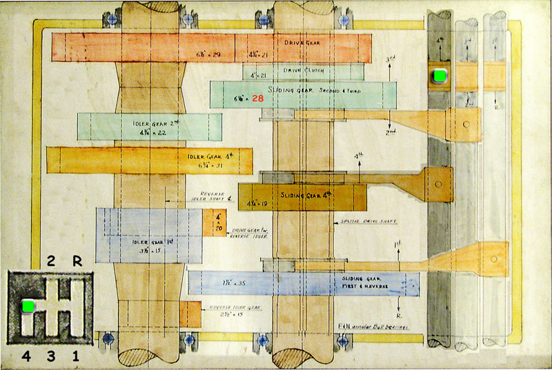
| John Millerbough's 1957 drawing of a 4-40 transmission. (Image courtesy of Andrew Wilson) |
Last update: Jan. 5, 2009
| Jump to: | |
| Overall Description | |
| Joe Finds an Error | |
| Final Drive Ratio | |
| Diagramming the Power Flow | |
Andrew Wilson provides Lynn with a drawing made by John Millerbough of the transmission in Herman, his 1914 Kissel 4-40 Touring. This is an important addition to Lynn's technical information on Annie and he spends some time examining it. Although an important error comes to light in the process, Lynn gains some valuable new information and insight into the operation of his new (old) car.
Overall Description
The following table summarizes the gear ratios for the transmission.
Gear |
Ratio |
1st |
3.22 |
2nd |
1.75 |
3rd |
1 |
4th |
0.85 |
Reverse |
4.30 |
John's diagram shows the transmission in neutral.
On the left side of the diagram is the IDLER SHAFT and the REVERSE IDLER SHAFT (lower left of drawing, hidden below the IDLER SHAFT).
In the center of the diagram is the INPUT SHAFT (a short shaft on the top) and the OUTPUT SHAFT (a long shaft on the bottom). Although the INPUT SHAFT and OUTPUT SHAFT share the same centerline, the center shaft is not continuous, but it is split into two parts just below the DRIVE GEAR.
Along the right side of the diagram are three gear SELECTOR SHAFTS which move sliding gears via an attached fork. The transmission shift handle is designed so that only one selector shaft can be changed at a time. The shift handle (and an associated SELECTOR SHAFT) must be returned to the neutral position before it can be slid sideways to engage another SELECTOR SHAFT. This arrangement results in a bulky and show shifting transmission.
For 1st gear, SLIDING GEAR 1ST & REVERSE (blue) is moved upwards to mesh with IDLER GEAR 1ST (blue). The power flows through the INPUT SHAFT, to the IDLER SHAFT and out through the OUTPUT SHAFT. The resulting gear ratio for 1st is 3.22~(29/21)*(35/15).
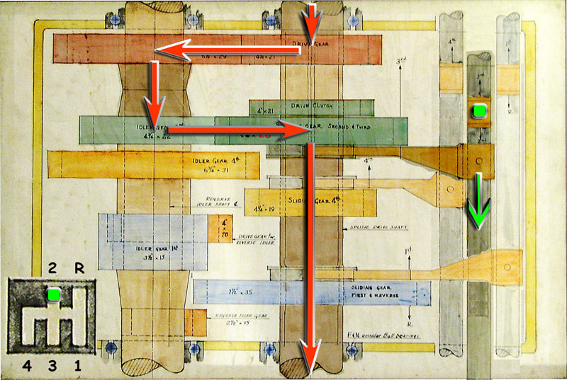
For 2nd gear, the gear cluster containing SLIDING GEAR 2ND (green) is moved downwards to mesh with IDLER GEAR 2ND (green). The power flows through the INPUT SHAFT, to the IDLER SHAFT and out through the OUTPUT SHAFT. The resulting gear ratio for 2nd is 1.75~(29/21)*(28/22). (Note that the number of teeth on SLIDING GEAR 2ND shown in the diagram is in error as noted below.)
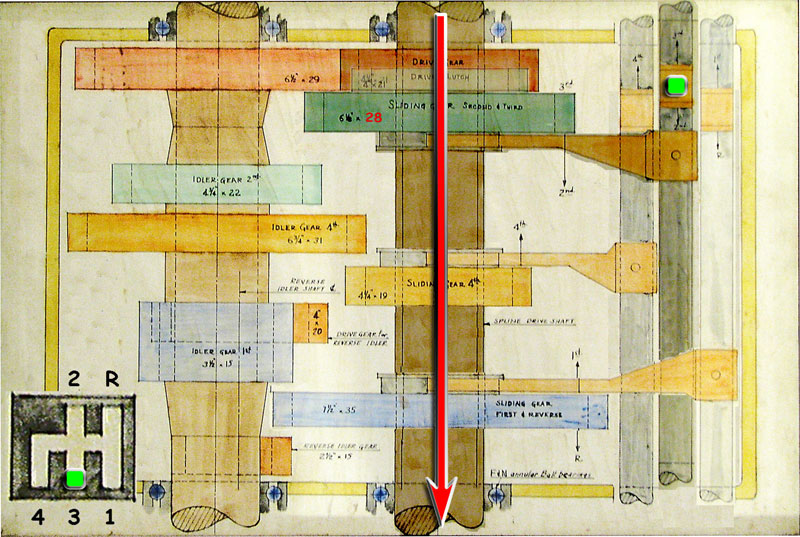
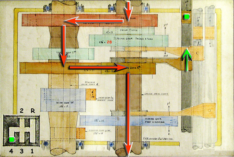
For 3rd gear, the gear cluster containing the 3rd gear DRIVE CLUTCH (green) is moved upwards to mesh with a recess machined in the DRIVE GEAR (red). The power flows directly from the INPUT SHAFT to the OUTPUT SHAFT resulting in a direct 1:1 gear ratio.
For 4th gear, SLIDING GEAR 4TH (orange) is moved upwards to mesh with IDLER GEAR 4TH (orange). The power flows through the INPUT SHAFT, to the IDLER SHAFT and out through the OUTPUT SHAFT. The resulting gear ratio for 4th is 0.85~(29/21)*(19/31).
For reverse, SLIDING GEAR 1ST & REVERSE (blue) is moved downwards to mesh with REVERSE IDLER GEAR (dark orange). The power flows through the INPUT SHAFT, to the IDLER SHAFT, to the REVERSE IDLER SHAFT and out through the OUTPUT SHAFT. The resulting gear ratio for reverse is 4.30~(29/21)*(20/15)*(35/15).
Unfortunately, although they are only sometimes involved in the power flow, the IDLER SHAFT and REVERSE IDLER SHAFT are always spinning. This results in wasted energy.
Joe Finds an Error
Lynn discusses the diagram at length with his friend Joe Leaf. Joe points out a number of important technical aspects of the drawing and notes an important error.
The diameters of gears shown in the drawing are likely approximate outer diameters measured by John Millerbough with a ruler. A second number indicates the number of teeth on the gear. For example, the item labeled 'DRIVE GEAR, 4-1/2"x21' is a gear with an outer diameter of approximately 4.5" with 21 teeth.
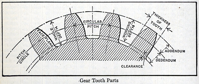 |
Gear tooth parts (from Machinery's Handbook).
|
Instead of an outer diameter, a machinist would specify the pitch diameter, D=N/P, where N is the number of teeth and P is the diametral pitch. (See, for example, Machinery's Handbook). The pitch diameter is the imaginary circle (about 1/2 down the face of the gear tooth) where meshing gears "touch". That is, one-half the sum of the meshing gears pitch diameters is the design distance between their centerlines.
Assuming that Kissel used a standard for these gears, this transmission is likely a 5 dp (diametral pitch) gear set. For the 21-tooth DRIVE GEAR, the pitch diameter would be 4.2"=21/5. The addendum (height of tooth above the pitch diameter) for a 5 dp gear is about 0.2", so the outer diameter of this gear would be about ~4.4"=4.2"+~0.2", in fair agreement with John's 4.5" notation.
If the assumption of a 5 dp gear set is true, one can immediately determine the distances between the centerlines of the three shafts shown in the drawing: 5"=0.5*21/5+0.5*29/5 between the INPUT SHAFT or the OUTPUT SHAFT and the IDLER SHAFT; 3.5"=0.5*15/5+0.5*20/5 between the IDLER SHAFT and the REVERSE IDLER SHAFT; 5"=0.5*15/5+0.5*35/5 between the REVERSE IDLER SHAFT and the INPUT SHAFT or the OUTPUT SHAFT.
There is an error in the tooth count of one of the two gears labeled IDLER GEAR 2ND (4-3/4"x22) and SLIDING GEAR SECOND & THIRD (6-1/8"x21). Since these gears are intended to mesh, the larger gear will necessarily have more teeth than the smaller one which is inconsistent with the teeth count shown in the diagram.
The sum of the teeth for other mating gears in this transmission between the INPUT SHAFT or the OUTPUT SHAFT and the IDLER SHAFT is 50. If this gear set in indeed 5 dp, the error is in the SLIDING GEAR SECOND & THIRD and it must have 28=50-22 teeth.
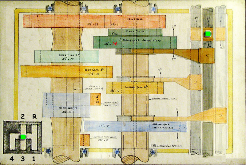 |
Transmission diagram with correct tooth count on SLIDING GEAR SECOND (in red).
|
It seems likely that the error is a transcription error. One notes that the drive gear and drive clutch both have 21 teeth. It's likely that John simply transferred the wrong number to his drawing from his worksheet where he jotted down his measurements.
Final Drive Ratio
John Millerbough notes a final drive ratio of 4 in the upper-left corner of his drawing. If this is accurate, it is an important piece of information that Lynn has not be able to find elsewhere. For example, none of the specifications that he's been able to find in the Kissel files at the Wisconsin Automotive Museum note final drive ratios.
In a descriptive text file on Annie written by Ann Klein, it is noted that the original differential ring gear suffered several cracked teeth that were initially repaired by welding. Sometime later a replacement ring and pinion gear set was found and installed in Annie. The new set had a higher ratio number than the original set, but Ann doesn't mention the value of the original or new final drive ratio.
Lynn is suspicious that John's final drive ratio of 4 is only an approximate value, maybe obtained by counting rotations of the drive shaft relative to the rear wheels rather than an exact value based on counting gear teeth. In his experience he has never know a final drive ratio to have such an even, whole-number value.
Lynn has begun asking other Kissel owners about their final drive ratios to see if he can confirm John's value or establish some pattern. The following table summarizes what he's been told to date.
| Year | Model | Final Drive Ratio | Owner |
|---|---|---|---|
| 1911 | LD-11 Semi-Racer |
3.73 |
Steve Mergele, Boerne, TX |
| 1912 | 4-50 Semi-Touring |
4.25 |
Vic Groah, Tulare, CA |
| 1914 | 4-40 Touring |
3.5 |
Andrew Wilson, Brunswick, ME |
| 1924 | 6-55 Speedster |
4.09 |
Lynn Kissel, Livermore, CA |
Diagramming the Power Flow
The following illustrations show the changing gear positions and flow of power through the transmission as one shifts the gears.
(If you click on a thumbnail and uses the keyboard shortcuts N and P to scroll through the larger images, you can almost visualize the gears shifting and meshing in the transmission. Of course, to be completely realistic, you should make some gear clashing, crashing and grinding sounds with your mouth to simulate how well such a nonsynchromesh, sliding-gear transmission shifts in practice.)
 |
 |
||
| Shift from neutral to 1st gear. | |||
|
|
 |
|
| Shift from 1st to 2nd gear. | |||
|
 |
||
| Shift from 2nd to 3rd gear. | |||
|
 |
 |
|
| Shift from 3rd to 4th gear. | |||
|
|
|
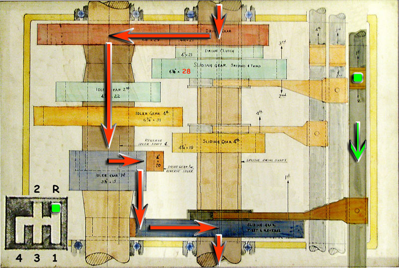 |
| Shift from 4th to reverse. | |||
The power flow through this transmission starts at the center-top of the drawing with the INPUT SHAFT which is connected off the top of the drawing on a 1914 4-40 Kissel by a short drive shaft containing a universal joint to a cone clutch. The INPUT SHAFT is very short, it is only connected to the DRIVE GEAR (red, 21 teeth) through which it drives the IDLER SHAFT (long shift with four fixed gears on the left side of drawing).
The four gears fixed to the IDLER SHAFT, top to bottom, are the IDLER DRIVE GEAR (red, not labeled, 29 teeth), the IDLER GEAR 2ND (green, 22 teeth), the IDLER GEAR 4TH (orange, 31 teeth) and IDLER GEAR 1ST (blue, 15 teeth). The IDLER SHAFT drives the REVERSE IDLER SHAFT (lower left of drawing, hidden below the IDLER SHAFT).
The REVERSE IDLER SHAFT is relatively short and has two fixed gears at either end, a DRIVE GEAR (dark orange, 20 teeth) which meshes with IDLER GEAR 1ST and a REVERSE IDLER GEAR (dark orange, 15 teeth).
The OUTPUT SHAFT is the long center shaft that transfers power out of the bottom of the transmission. Off the bottom of the diagram it is connected to a drive shaft (with universal joints at both ends) which is, in turn, connected to the differential. The OUTPUT SHAFT has three sliding gears which are, top to bottom, a gear cluster containing the SLIDING GEAR 2ND (green, 28 teeth - error in the diagram, see below) and 3rd gear DRIVE CLUTCH (green, 21 teeth), SLIDING GEAR 4TH (orange, 19 teeth) and the SLIDING GEAR 1ST & REVERSE (blue, 35 teeth).
Contact
 with your comments or questions
Copyright © 2018 Lynn Kissel
Last updated: May 24, 2009