The Serious Freshening
Go to <Last, Summary, Next>
Interior—Wiring
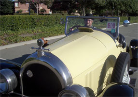
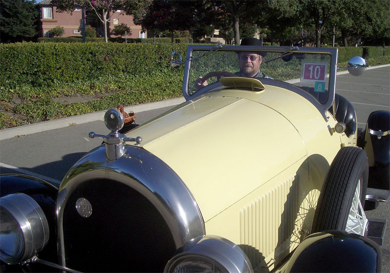
Lynn in Bugsby, September 5, 2005
|
Completed: 2008-04-06 — Started: 2007-08-25
|
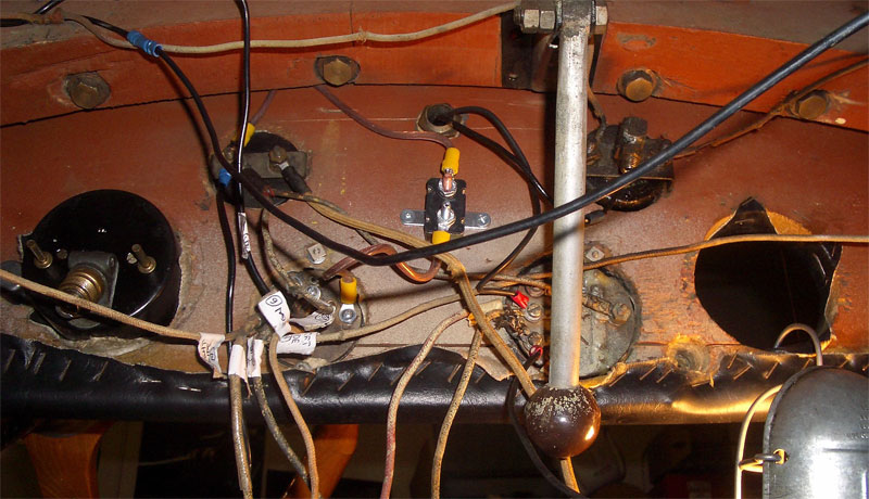
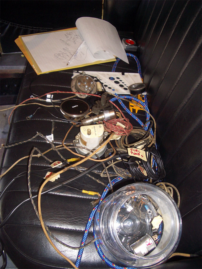
OLD WIRING:
The old instrument panel wiring (left) and wires removed from Bugsby (right).
(Photos taken Jan. 2006.)
|
|
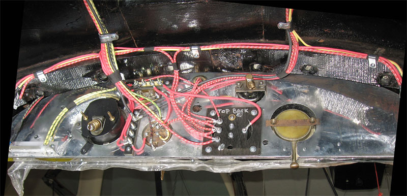
NEW WIRING:
New wires on instrument panel (left) and firewall (right). The protective plastic film on the
new instrument facia has not yet been removed. (Photos taken Dec. 2007.)
|
Work Completed:
Lynn got the freshly painted body
of Bugsby back in his garage in mid July 2007.
As he begins to fit the body onto the frame, he realizes that this is a perfect time to perform
the electrical wiring.
Now he can lift the body and walk under the instrument panel.
If he waits until later after everything is bolted back on the frame, he will lying on his back with
his head under the instrument panel in one of the most uncomfortable positions known to man.
In addition to simply restoring the original electrical system of Bugsby, Lynn wants enhance the
lighting system much like the
enhanced wiring he
created for Penny.
His planned enhancements include:
- new rear turn/stop/tail lamps at the corners of the rear bumper;
- new front turn/park lamps at the corners of the front bumper;
- an electronic turn-signal and 4-way-flasher controller;
- circuit breakers and relays to support high current (bright) headlights;
- a circuit breaker and relay to support add-on fog or driving lights.
To the extent possible, Lynn will make these enhancements invisible to the casual observer,
attempting to preserve Bugsby's unmolested character and allowing for participation in judged
car shows.
|
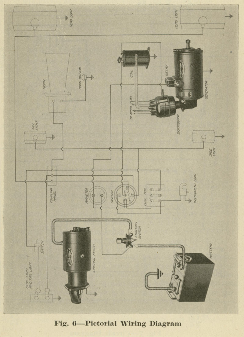
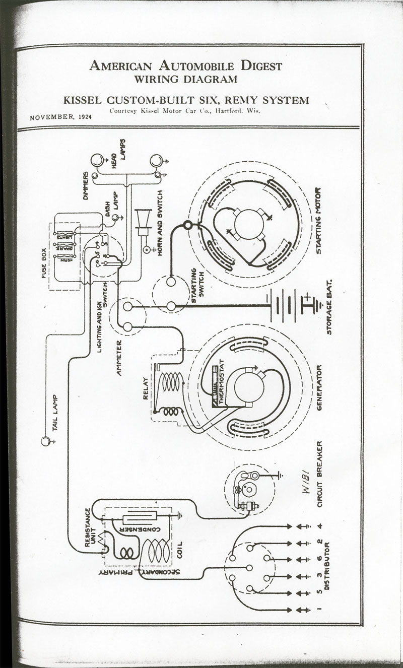
REFERENCE WIRING DIAGRAMS:
Kissel Instruction Book No.7
has this pictorial wiring diagram (left).
The American Automobile Digest from November 1924 has this equivalent wiring diagram (right).
|
| |
|
NEW WIRING DIAGRAMS:
Lynn created these drawings with detailed plans for the wiring job ahead.
Click on these links for a PDF copy of the chassis (30 KB) and
instrument panel (30 KB) wiring plans.
|
|
Lynn creates detailed wiring diagrams for the chassis and instrument panel.
While time consuming, this planning exercise significantly improves the quality of the resulting job.
It is much easier to reroute wires and change color and gauge of wires on a computer drawing than to
do it with the physical wires.
Indeed, Lynn makes lots of changes to his plan before he actually heads for the garage.
Lynn is really pleased to discover
Narragansett Reproductions,
a great source for cloth covered wire and antique car wiring harnesses.
Unlike other sources that he has found, Narragansett can produce nearly any combination of wire gauge, primary color and secondary colors in a wide variety of patterns (straight trace, double trace, cross trace, double cross, fifty-fifty, etc.).
In addition, these people have some of the most reasonable prices that Lynn has encountered.
|
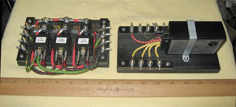
DAUGHTER BOARDS FOR MODERN ELECTRONICS:
Small boards are build to hold the modern electronics.
|
| |
|
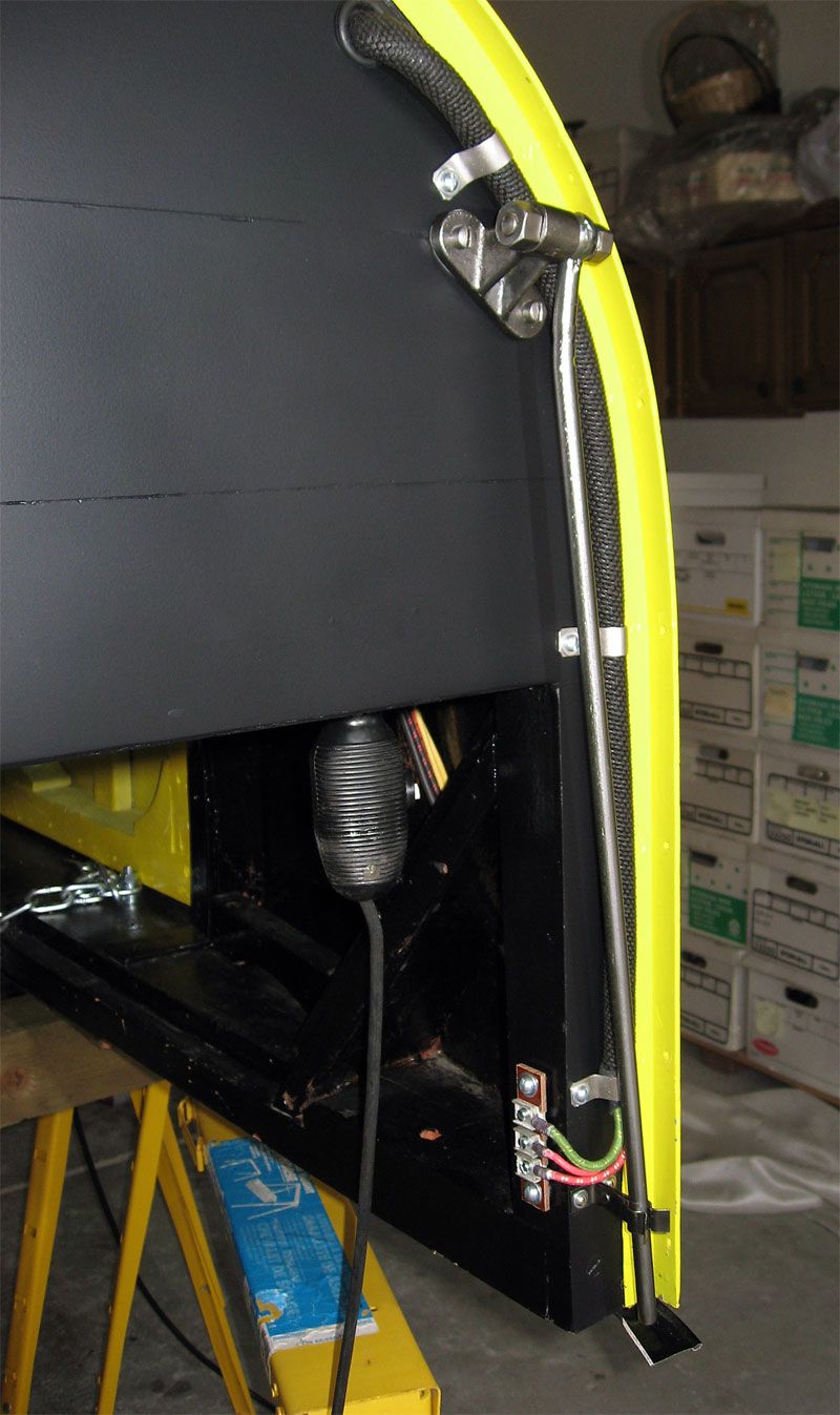
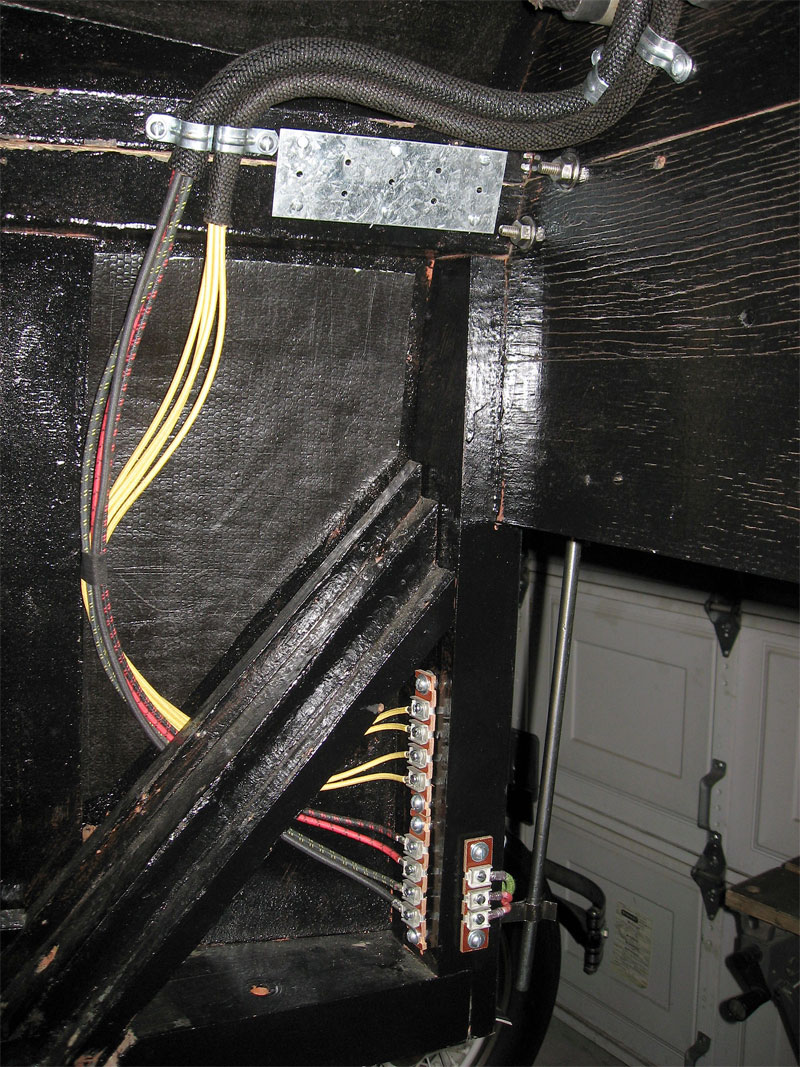
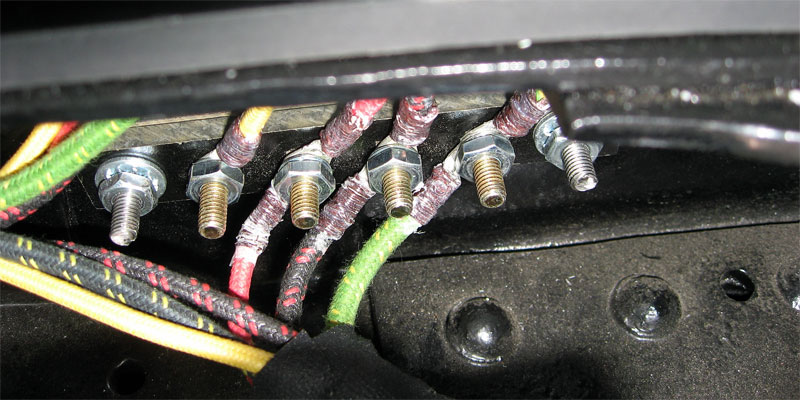
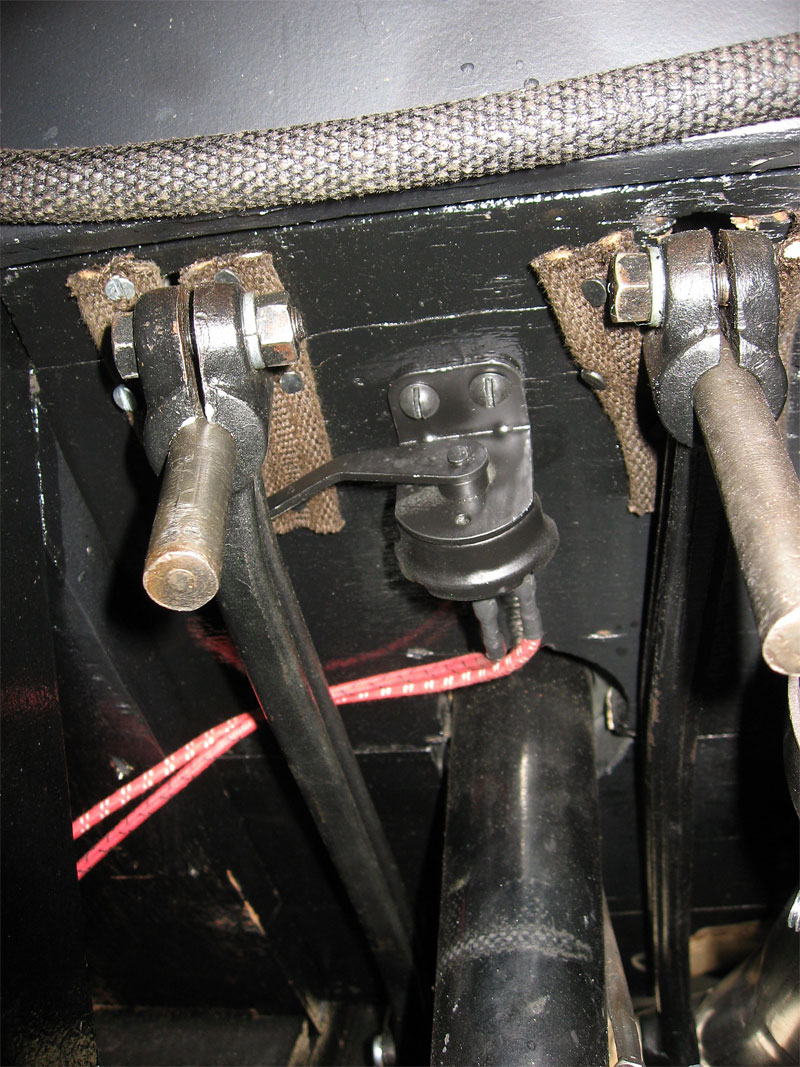
HIDING THE EXTRA WIRES:
The casual observer will see only the traditional three-wire block on the left side of the
firewall (left) unaware of the larger number of new wires which are "hidden" on the back side (center).
Additional hidden junction blocks are also installed at the four corners of the frame (right)
and on the right side of the firewall.
|
|
Armed with a plan and parts he needs to perform the wiring, Lynn starts serious wiring work in Oct. 2007.
He wants to keep any modernizations to Bugsby reversible and separable so he mounts his modern electronics
on small daughter boards.
The idea is that it would be a reasonably simple matter to remove these boards to restore the car to
a more authentic state if that becomes desirable.
The added stop/park/turn/fog lights and revised brake switch require quite a few extra wires.
To the extent possible all these extra wires are hidden from view, tucked inside the frame or within
autoloom (asphalt covered cotton sheaths) which he uses between major wiring points.
|
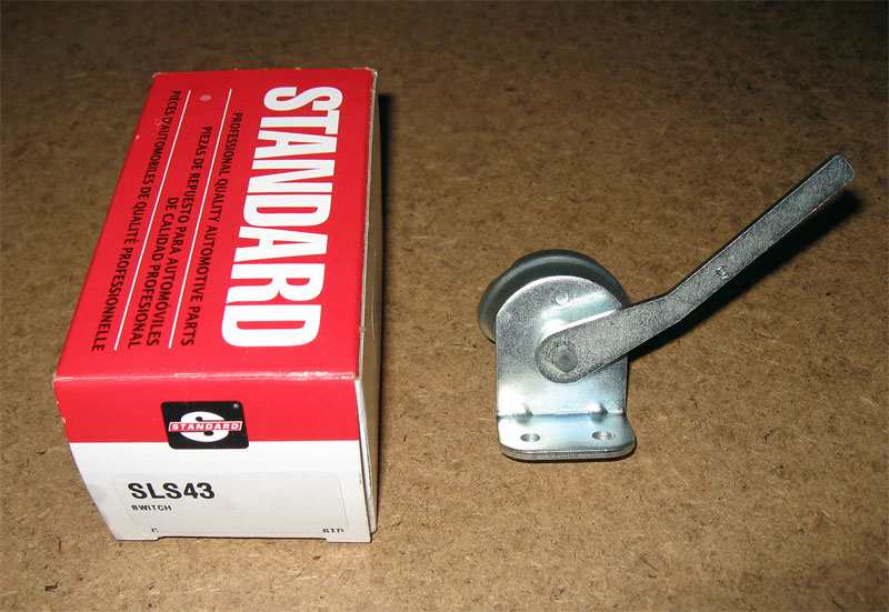
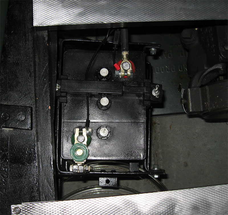
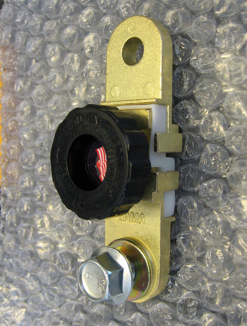
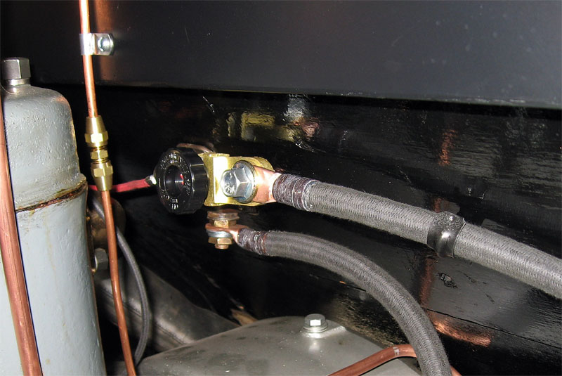
SAFETY IMPROVEMENTS:
Lynn installs a more modern brake switch (left two photos) and battery switches (right three photos).
|
Lynn takes the time to make some other electrical enhancements.
He installs a new brake switch (from a mid-1950's Chevy truck) to the floor boards.
This switch is much more reliable than the one he originally found on the car.
He considers this an important safety enhancement as he can display brake lights as a warning to
those behind him on the road without actually engaging the brakes.
Lynn considers a battery switch to be a critical safety item, especially when the car is on display at a show
or when he is working on the vehicle.
With the battery completely disconnected from the rest of the electrical system, one can be reasonably confident
that nothing will short or start as one is poking around on the car.
Lynn installs a battery switch on one of the posts of the battery.
This turns out to be relatively useless as the battery is located under the floor boards
and it's too inconvenient to access the switch.
Lynn buys a second switch built for a side-post battery and mounts this one to the starter switch.
Located under the floor boards just under the bottom of the firewall, this second switch
is easily accessible when the hood is open.
Work Remaining:
None.
Contact  with your comments or questions with your comments or questions
Copyright © 2018 Lynn Kissel
Last updated: May 24, 2009
|